In the box modeling, you need to commonly adhere to some steps for receiving impeccable results.
Setting up the Work Environment
First, you need to search for relevant and attractive reference materials that can be applied to the desired things to model in 3D. Then, you need to set up multiple views or angles of the model and prepare a plan about how you are going to proceed. You can also get the best 3d product visualization services via vizframe.com/3d-product-configurator-online/.
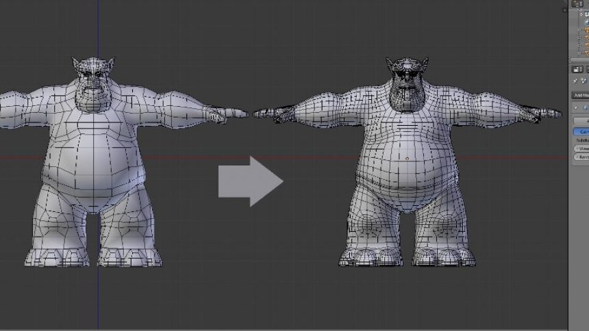
Image Source: Google
Now, map the level of detail required and the steps involved in achieving the same. Finally, you can try working out the method that would allow faster and easier implementation of box modeling.
After setting the work environment optimally, place the reference image in the background. Setting up all the shortcuts and layout-related expedients, choose a basic shape in the 3D software which would lead to the faster completion of the draft.
Defining the Rough Draft:
Try defining the rough draft by making customized segments or iterations to the basic shape.
In 3DS Max, the iterations can be created from the Command Panel or on the Create/ Modify panel.
With Insert Face, you can develop a face that is evenly formed into another for the ease of extruding in or out. This would provide more symmetry to the shape’s geometry.
In 3DS Max, the edge can be added with the ‘Connect Vertices’ command. It also allows for defining or controlling any four-sided polygon’s tessellation.
Rough Detail Stage:
The rough model achieved so far can be refined by repeating the above steps. Apart from that, below are some other tools that are commonly used at this stage.
Gaps created due to face deletion can be filled with ‘Create Face’. Try using the command on faces in the clockwise mode to target the visible faces.
Edges can be rounded off or two edges can be formed out of one with the ‘Chamfer Edge’.
If the model form is set and some vertices or edges have to be moved a little, the same can be done with 3DS Max modeling techniques by using the Constraints tool.
The path along which the edge of the face or vertex has to be moved can be defined using constraints.
The face which has been oriented wrongly can be corrected using Flip Face or Normal command.